


INTRODUCTION
At the time that the ‘Agile Manifesto’ [1] was proposed, there was a big shift to focusing on delivering software and away from heavy technical documentation and specifications. Based on one of the values of the Manifesto, ‘Working software over comprehensive documentation’, specification of requirements has been reduced to a minimum. This does not mean that requirements specification models do not provide useful inputs if software teams adopt Agile software development (ASD) lifecycles (e.g., Scum, XP, Kanban, SAFe, LeSS, etc.) in a project or in product development.
In change-driven approaches, like ASD, RE discipline – also called “Agile RE” – activities are executed continuously [2] in an iterative discovery approach [3]. Additionally, requirements modeling must follow an agile approach in order to prevent unnecessary efforts in “You Aren’t Gonna Need It” (YAGNI) features, by avoiding big design upfront (BDUF), producing information for teams in a just-in-time (JIT) fashion and providing inputs at the last responsible moment (LRM).
This article discusses how elicitation, analysis, specification, validation, and management of requirements must have in mind to avoid “waste” tasks that lead to those YAGNI features. By adopting practices and mindsets from approaches like Lean Startup, Design Thinking, Domain-driven Design (DDD), Behavior-driven Development (BDD), Kent Beck’s 3X and BizDev, RE professionals may elicit and model requirements without losing the agility of the process (and hence Agile RE practices), taking advantage of some of their useful practices in the elicitation phase and analysis phase. It presents practical discussions about how each of the aforementioned approaches impacts - both in eliciting (and discovering) and in analysis – requirements engineering tasks, using a running example from a real industrial project. The presented example includes models such as scenarios (in a special type of UML Sequence diagram), UML Use Cases diagrams, and UML Components diagrams. Firstly, these agile practices are introduced and how they fit in requirements elicitation and management. A further discussion of both of these phases is presented, by taking advantage of these agile practices. Finally, the article ends with the key takeaways of adopting these practices.
AGILE PRACTICES AND RE
Models, such as UML, still have an important role in ASD-oriented requirements and analysis, whether in the discovery or the delivery phases [4]. The goal of RE activities in ASD lifecycles is to iteratively elicit and model requirements as they emerge. The agility within RE practices is promoted by including agile practices and mindsets, namely from approaches like Lean Startup [5], Design Thinking [6], Domain-driven Design (DDD) [7], Behavior-driven Development (BDD) [8], Kent Beck’s 3X [9] and BizDev [10]. Additionally, user requirements should be delivered in small increments and ready for continuous customer feedback. The mentioned approaches are now briefly introduced.
DDD is an approach that proposes the division of concepts by domains, or sub-domains, if applicable. This separation of domains is useful for defining clearly the scope of application for a given requirement. DDD has gained some attention because it promotes each team to work independently inside their bounded context (Figure 1.a).
Design Thinking addresses understanding the customer need through systematic exploration. The objective is to understand what the right product is. This approach encompasses “Empathize”, “Define”, “Ideate”, “Prototype” and “Test” phases (Figure 1.b).
BDD is an agile practice that consists in defining increments of software behavior (Figure 1.c). Similar to BDD, Test Driven Development (TDD), Acceptance Test Driven Development (ATDD) and Specification by Example (SBE) use testable scenarios as input for the software development. All of them have in common a development based on scenarios and use of the “Given, When, Then” (gherkin language).
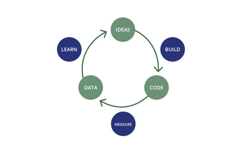
Lean Startup is a hypothesis-driven approach, where a "Build-Measure-Learn" cycle is the basis for developing a product that is adequate to the market (Figure 1.d).
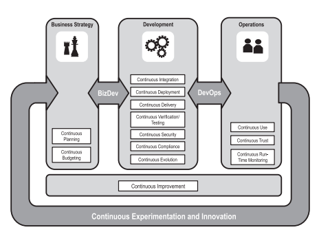
BizDev is a framework that provides a continuous linking of Business Strategy & Planning and Development (Figure 1.e).
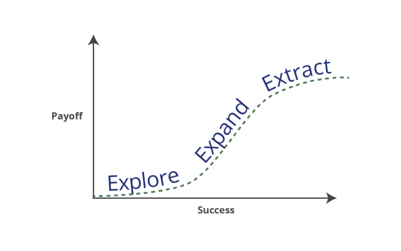
3X relates to Beck’s vision of three phases for a successful product development: explore, expand, extract (Figure 1.f).
Overview of the six analyzed agile practices
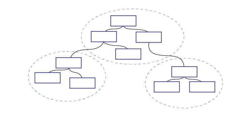


These agile practices cover - partially or completely – the product development lifecycle, from ideation through delivery to feedback gathering. Depending on this coverage, applying the practices themselves in requirements engineering can be more appropriate either when eliciting and discovering, or when analyzing and modeling. Table 1 depicts how each agile practice fits, whether in elicitation and discovery of requirements or in requirements analysis and modeling.
| Agile Practice | Elicitation & Discovery | Analysis & Modeling |
|---|---|---|
| DDD | Domain boundaries | |
| Design Thinking | Empathize, Define, Ideate | Prototype, Test |
| BDD / TDD / ATDD / SBE | Discovery and definition of scenarios (in gherkin format) | |
| Lean Startup | Build | Build, Measure, Learn |
| BizDev | Business Strategy & Planning, Development | |
| 3X | Explore | Extract |
Table 1: Phases of the agile practices
RUNNING EXAMPLE: THE UNIFIED HUB FOR SMART PLANTS (UH4SP)
The UH4SP [11] project aimed to develop a platform for integrating data from distributed industrial unit plants, with focus in the cement domain, by using data acquired from IoT systems for enterprise-level production management and collaborative processes between plants, suppliers, forwarders and clients. The project encompassed new solutions for controlling trucks’ arrival/exit and their load/unload activities and for communicating with the plant’s ERP and the industrial hardware. The production management systems that were used were developed by Cachapuz Bilanciai Group, located in Braga, Portugal, as they were the leading entity of the UH4SP project consortium.
In short, the UH4SP project aimed to develop:
- new functionalities for management of corporate-level production;
- tools for supporting new collaborative processes within the supply chain;
- a microservices architecture;
- production management services, that rely on previous synchronization of Cachapuz’s systems (at the industrial unit level).
ELICITATION AND DISCOVERY PHASE
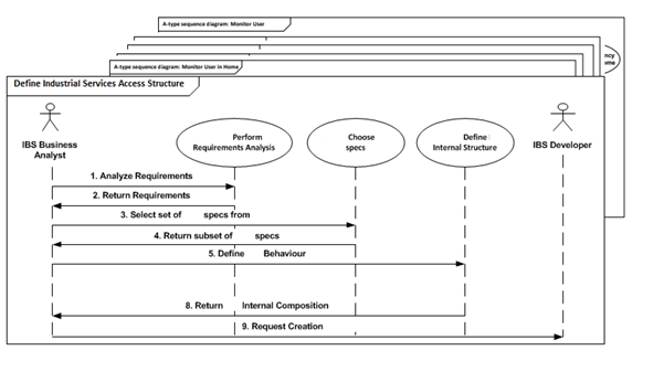
The elicitation and discovery phase involves eliciting customer needs, exploring alternatives and discovering new requirements, all in alignment with current agile practices from ASD frameworks, techniques and philosophies. These activities are the result of several interactions with stakeholders - customers, users, domain experts, security and data privacy experts, technical experts, COTS experts, etc. Requirements engineering focuses on eliciting as much data as possible, facilitating and promoting discussions, gathering all information and ultimately capturing it in the form of models. With this goal in mind, this phase outputs a set of scenarios, i.e., processes and activities performed using the solution under development. These scenarios are documented in A-type sequence diagrams [12], a stereotyped version of UML sequence diagrams that only includes actors and use cases, and where a business process sequential flow is described (but not technical – which is the case for B-type sequence diagrams [12], but they are out of the scope of this article). Because these diagrams are composed of actors, their activities and the flows, they are appropriate for this stage of the requirements process.
At this stage, the use cases included in these diagrams do not yet form part of the Use Case model from the next stage. Rather, they are classified as candidate use cases, because they relate to specific activities and tasks that a given actor performs (in software or not) within a given scenario. The flows between actors and candidate use cases relate to the actions performed. The reason for using these diagrams instead of UML Activity diagrams, BPMN, or any other process-oriented language, relates to the use of candidate use cases: These will be an input to the use case model that is to be modeled in the next phase, i.e., Requirements Analysis and Modeling).
Applying agile practices in this phase influences:
-
In Lean Startup, stakeholders define scenarios with an experimental mindset. At this point, stakeholders decide which features to include/experiment within a minimum viable product (MVP). An MVP is a version of a new product that is created with the least effort possible and that is delivered to customers so the company can receive fast feedback from the market. The scenarios for such features are elicited with what is known at the time, where the goal is not to have detailed technical description of how the solution will support such scenarios, but rather to define the referring processes. The remaining features may be refined afterwards.
-
In BDD (or TDD, ATDD or SBE), the requirements discipline is addressed in the discovery and definition of scenarios (in gherkin language format, which is a sentence containing inputs of “Given, When, Then”). This format is mapped in A-type sequence diagrams, where “Given” contextualizes each sequence diagram, “When” relates to a main sequence, or alternatively to an optional or exceptional sequence (if existing), and “Then” relates to the flows within the diagram.
-
In Design Thinking and Kent Beck’s 3X, the stakeholders’ desires and expectations are included in the scenarios, but the idea is also to discover and explore scenarios with different solutions and processes rather than only address what customers dictate. From these agile practices, it must be pointed out that the differentiator practice is that of discovering what users need (“empathize”). These discussions promote discovering and exploring additional and alternative scenarios beyond only those ones that could be discussed at a first sight. Thus, new process flows are incrementally discovered, and new A-type sequence diagrams are added throughout this process - as depicted in Figure 2.
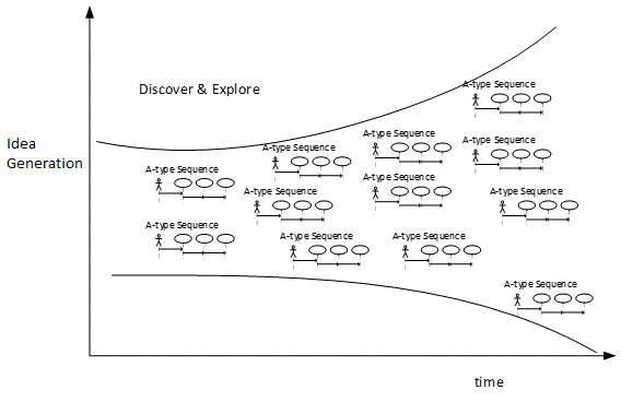
These scenarios, right or wrong - bear in mind that this is an exploration phase - are modeled in A-type sequence diagrams. These diagrams are the first visual prototype for which customers are able to provide feedback. As is widely known, fast feedback is one of the key suggestions of ASD.
In our running example the UH4SP project consortium is composed of five different teams for software development, each with its own specialty, from cloud architectures to industrial software services and mobile applications. A cross-team analysis group (composed of people from each team) conducted the requirements phase, with the aim of defining initial requirements.
The requirements elicitation started by listing a set of stakeholders' expectations towards the product roadmap, encompassing the entire product, but with only MVP features detailed. The list included 25 expectations categorized by environment, architecture, functional and integration issues, which related to business needs that later prompted the discussion of scenarios. These scenarios were elicited jointly with the customer, where not only their initial needs were gathered but also where alternatives existed these were explored. At this point, 15 A-type sequence diagrams were modeled, as shown in Figure 3, divided into four groups of scenarios (which relate directly to the project’s four objectives).
REQUIREMENTS ANALYSIS AND MODELING PHASE
In the Requirements Analysis and Modeling phase, the tasks are supported by requirements models. In this article, we discuss modeling requirements in a UML Use Case diagram. Using as input the elicited scenarios, namely the models from A-type sequence diagrams, the Use Case diagram is built and each use case refined. The gathering of candidate use cases from the sequence diagrams into the use case model is based on a set of decisions that use agile practices from Design Thinking and DDD approaches.
In this phase, candidate use cases from A-type sequence diagrams will give rise to “typical” use cases. The idea is to use all modeled information and to use it to model and refine use cases. The detailed information corresponds to a use case, functionally decomposed by the sub-domains comprising a domain or by parts of a process. In this way use cases are refined in decomposition trees. Each branch is composed of a decomposition of use cases. The candidate use cases from A-type sequence diagrams are logically grouped, typically according to the scenario from the A-type sequence diagram where they originated.
Applying agile practices in this phase influences:
- In Lean Startup, as stakeholders define which scenarios to include in an MVP, they are expressed in more detail unlike the scenarios that are left out of the MVP at this phase. Thus, there is more context to define the models that will compose the MVP. The use cases will be more decomposed because there are more agreed requirements. The requirements that are not refined for the MVP are still identified but will not be decomposed.
- In Design Thinking, use cases are used as design prototypes that are presented to stakeholders for first feedback.
- In BizDev, use case models trace back to the scenarios, which support the continuous linking of Business Strategy & Planning (from the scenarios we aim to cover) and Development (from the development scope defined by the use cases).
- In DDD, the candidate use cases from A-type sequence diagrams are grouped in domains and sub-domains. The refinement “branches” of the decomposition tree will relate to a single domain or sub-domain, hence defining bounded contexts for a (sub-)domain. Bounded contexts allow each (sub-)domain to be addressed independently, by team members or by different teams.
In the case of the UH4SP project, the 15 A-type sequence diagrams from the Elicitation and Discovery phase were gathered in a decomposition tree composed of 37 use cases after the refinement. Figure 4 is not zoomed since the objective is to present the refinement levels, their inclusion in the MVP and the identification of DDD’s bounded contexts, rather than the details of the use cases.
The impacts of agile techniques in modeling the UH4SP use cases were:
- By applying DDD, use cases are grouped by the domains and sub-domains. This means that each of the tree’s “branches” relate only to a given domain, which also assures that the contexts are properly bounded. Each bounded context is represented as in Figure 4. The identified domains relate directly to the four scenario groups. Two of them - “tools for third-party entities” and “system reliability” - were later divided in two and three domains respectively, making a total of seven. Two of the “system reliability” bounded contexts are not even depicted due to MVP decisions.
- By applying Lean Startup, the features defined for the MVP are identifiable in the model as those having refined use cases, while the remainder only show the first-level. Use cases {UC.3} and {UC.4} relate to features not addressed in the MVP, and hence were not the object of further decomposition. The remaining use cases were included in the MVP, namely: {UC.1} was decomposed in five use cases, {UC.2} was decomposed in eight use cases, {UC.5} was decomposed in two use cases, {UC.6} was decomposed in five use cases, and {UC.7} was decomposed in ten use cases.
Figure 4: Use case decomposition tree of UH4SP, the Use cases from MVP features (Lean Startup), and the domain's and sub-domain's bounded contexts (DDD) - picture available in: shorturl.at/yEYZ7
“JUST-ENOUGH” MODELING
We must now decide when the “just-enough” requirements model is complete. In an agile context, where the requirements are not known upfront, it is very difficult to know in advance how much RE is “just-enough”. The vision document, for instance, reflects stakeholders’ intentions (i.e. features) towards the entire product, however the main purpose at this time is to ensure that such features are included. At this point, stakeholders have decided which features to include in the MVP. The requirements that are the object of “just-enough” refinement and modeling relate to such features. The remaining features from the product roadmap may be refined afterwards.
Although a process based on stakeholders’ expectations is presented, any business requirements-related information or documents that provide inputs for the software requirements elicitation are useful for validating high-level requirements. Techniques like interviews, questionnaires, workshops, etc., are complementary approaches to this document analysis for gathering inputs on requirements. The use of these techniques is a decision for RE professionals as they look for the best fit in a given context.
During the Requirements Analysis phase (previous section), use cases are decomposed once or twice, instead of several times as in upfront approaches. Since the main idea is to model “just-enough”, one decomposition may be sufficient, namely the one of which stakeholders are aware at this point.
To validate if the modeled use cases cover the requirements defined in the product scope, Table 2 shows an example of the cross-checking between stakeholders’ expectations and the project goals with the use cases. Since the expectations and goals list emphasizes the MVP features, a context is provided for MVP features to be further decomposed than other features. The premise is that all these concerns are included in the Use Case model. With more emphasis on decomposition detail for MVP requirements, one may consider that we have “just-enough” requirements information for this stage.
| Req. | Expec. 1 | Expec. 2 | Expec. 3 | Expec. n |
|---|---|---|---|---|
| UC.1 | x | |||
| UC.2 | x | |||
| UC.3 | x | |||
| UC.n | x | x |
Table 2: Traceability matrix of requirements within the initial expectations
As in any requirements process, one of the first critical tasks is to identify all the project’s stakeholders, as well as the actors who will interact with the solution. By mapping stakeholders to the use cases (Table 3), one must ensure that every stakeholder/actor has at least one use case mapped to him/her, otherwise it is an indicator that critical requirements may be missing.
| Req. | Stkh A | Stkh B | Stkh C | Stkh D |
|---|---|---|---|---|
| UC.1 | x | |||
| UC.2 | x | x | ||
| UC.3 | x | |||
| UC.n | x |
Table 3: Traceability matrix of requirements within the project stakeholders and solution actors
The mappings from Table 2 and Table 3 validate that the UML Use Cases diagram includes not only the detailed features for the MVP, but also every high-level feature from the product roadmap. Also, all stakeholders have related functionalities. Both tables provide the required traceability to the expectations and stakeholder/actor needs, which hence become the mechanism used to respond to changes. When applied to mid- and long-term projects, the approach supports updates of expectations and stakeholder/actor needs over time, as well as the inclusion of new use cases, by tracing requirements in Table 2. Additionally, the approach leads with organizational changes, by tracing the use cases to stakeholder/actor needs in Table 3. This allows setting an initial set of use cases for the entire solution, and only assigning efforts for refining and prioritizing subsets of the model before beginning the implementation, in a JIT and LRM fashion.
In the UH4SP project during the first “Just-enough” modeling there were 37 use cases. We used this information for the architectural design, during which we modeled a UML Component diagram with 77 architectural components. A modularization of this architecture was performed, so that sub-systems of the architecture could be assigned to different teams, mainly referring to different high-level features (from the project’s four objectives). The refinement was performed incrementally and in parallel with the teams’ Scrum delivery iterations (Sprints). The requirements validation was thus iterative as well. One of those modules related to 11 use cases from the 37, and to 15 components from the 77. The requirements refinement that was performed after that resulted in 29 use cases, i.e. 18 refined functionalities, from which 37 new architectural components were then derived. That is an increase of almost three times compared to the original models. After modeling UML Use Cases, the requirements package was also enriched with wireframes, to enhance the discussion. Additionally, in Scrum’s Sprint Review and Retrospective ceremonies, these models were the object of discussion and feedback and, if applicable, missing requirements were added. These validations were crucial to getting buy-in of the complete team. The MVP, which supported the project’s pilot scenarios, was implemented at the end of these Sprints. The next releases according to the product roadmap are still to be developed.
TAKE-AWAYS AND FUTURE TRENDS
This article discussed the use of agile practices such as Lean Startup, Design Thinking, DDD, BDD, and others, during sequence, use case and components diagram modeling. Requirements engineering – both elicitation and analysis – is structured by modeling small chunks of requirements packages, which is an enabler for typical agile feedback loops. The approach also validated the coverage of the elicited “just-enough” model, gathered together with the identified key stakeholders, as a mechanism to prevent YAGNI.
Applying the above-mentioned practices had the following advantages for use case modeling:
- Overall, the use of agile practices per se did not make the process agile but allowed an agile specification of ‘the right product’ for the customer’s needs. It is possible to perform the proposed RE tasks if teams adopt any of the agile frameworks - Scrum, Kanban, XP, SAFe or LeSS, for instance - allowing the team to ‘deliver the product right’.
- Promoting scenarios discovery and exploration allowed the definition of 15 scenarios from four groups (from the project’s objectives). Without such exploring, each group would probably include one or two scenarios.
- Defining bounded contexts using DDD allowed a clear understanding of boundaries between the requirements different teams could address. The use of the Lean Startup strategy allowed refining of only the use cases from the MVP rather than all use cases.
- These practices eased stakeholder feedback - because the discussions were based on small chunks of requirements, which is fundamental in any ASD process.
- These practices allowed identifying what was the “just-enough” information and the requirements that should be refined (MVP), reducing waste and preventing modeling efforts on requirements that would later refer to YAGNI features.
The process described from the UH4SP project required a dedicated team for conducting these phases. In projects with more than one team, the dedicated team may be composed by representatives from the involved teams. Alternatively, each team could start defining requirements from the beginning, rather than starting with a “shared” model, as in our proposal. There is a need for future discussions of parallel emerging requirements, rather than starting with a single proposal.
The MVP requirements elicitation may be performed by gathering stakeholders’ individual needs, also referred to as “bespoke”, “custom” or “tailor-made” RE [13]. Alternatively, elicitation may be oriented to a mass-market where customers cannot be clearly pinpointed, also referred as “market-driven RE” (MDRE). This article is clearly based on bespoke RE. Future discussions are thus needed for elicitation that involves customers or other market entities (MDRE). Especially for companies adopting Lean Startup, which aim to launch their MVP without an identified customer to bespoke their requirements, MDRE will most likely be the required approach for RE.
REFERENCES
- [1] Agile Alliance. (2001). Manifesto for agile software development. agilemanifesto.org
- [2] Grau, R. & Lauenroth, K. (2014). Requirements engineering and agile development - collaborative, just enough, just in time, sustainable. International Requirements Engineering Board (IREB).
- [3] Cao, L. & Ramesh, B. (2008). Agile requirements engineering practices: An empirical study. IEEE Software, 25(1), 60–67. doi.org/10.1109/MS.2008.1
- [4] McDonald, K. J. (2015). Beyond requirements: analysis with an agile mindset. Addison-Wesley Professional.
- [5] Ries, E. (2011). The lean startup: How today’s entrepreneurs use continuous innovation to create radically successful businesses. Crown Books.
- [6] Brown, T. (2009). Change by Design: How Design Thinking Transforms Organizations and Inspires Innovation. New York: Harper Collins.
- [7] Evans, E. (2004). Domain-driven design: tackling complexity in the heart of software. Addison-Wesley.
- [8] Smart, J. F. (2015). BDD in Action: Behavior-driven development for the whole software lifecycle. Manning.
- [9] facebook.com/notes/kent-beck/the-product-development-triathlon/1215075478525314
- [10] Fitzgerald, B. & Stol, K.-J. (2017). Continuous software engineering: A roadmap and agenda. Journal of Systems and Software, 123, 176–189.
- [11] uh4sp.com
- [12] Ferreira, N., Santos, N., Machado, R. J., Fernandes, J. E., & Gasevic, D. (2014). A V-Model Approach for Business Process Requirements Elicitation in Cloud Design. Advanced Web Services, 551–578.
- [13] Fernandes, J. M. & Machado, R. J. (2016). Requirements in Engineering Projects. Cham: Springer International Publishing.

Nuno Santos is currently a Senior Business Analyst at Natixis Portugal. He holds a PhD in Technologies and Information Systems, and is also certified from Agile Alliance as CSPO, and from the IIBA as CCBA, AAC and POA. He has also written articles about requirements, agility and product ownership at RE Magazine, BA Digest, Analyst Catalyst, Medium, and in several scientific conferences.

Nuno Ferreira is currently the head of research at i2S Insurance Knowledge, invited professor at ISEP of Porto's Polytechnique Institute and researcher at ALGORITMI research center of Minho’s University in Portugal. He holds a PhD in Software Engineering. He has a strong background in software engineering, project management and process management. His re-search interests are requirements elicitation, process-to-product transitions, logical architectures derivation, and process maturity models.

Ricardo J. Machado is a full professor of Information Systems Engineering and Technology in the Dept. of Information Systems at the University of Minho (UMinho), School of Engineering. Within the Information Systems Engineering domain, his primary research interests are in modelling and requirements for systems analysis and design and in process and project management life-cycles. He has supervised 50 completed PhD and MSc theses in these areas. He has published over 150 scientific publications and 4 industrial patents, and has acted as coordinator (PI) and senior researcher of over 50 R&D projects. Currently, at UMinho he is the vice-rector for institutional development, the director of the ALGORITMI Research Centre, the scientific coordinator of the EPMQ Laboratory at the CCG/ZGDV Institute, the director of the Doctoral Program in Advanced Engineering Systems for Industry, and member of the Board of the UM-Cities Platform.