


The trend in systems engineering over the past decades has been towards ever increasing complexity, especially when considering the interaction of software components with other systems and physical mechanisms. One example of this is computational systems that are tightly integrated with physical processes, known as cyber-physical systems (e.g. modern automotive systems or robotics) (Lee, 2008). In cyber-physical systems, feedback loops typically exist in both directions, such that computational decisions affect physical elements and vice-versa. The consequence is that the cyber (computational) portion of the system cannot easily be considered – or verified – separately from the physical portion. This raises an important question: are current requirement engineering and verification practices sufficient to provide assurance on cyber-physical systems? The short answer is no; designing cyber-physical systems to high assurance or safety-critical levels with current practices is extremely challenging and prohibitively expensive. This expense will become progressively higher as the complexity increases in future generations of cyber-physical systems, and interaction between these systems becomes commonplace and unavoidable.
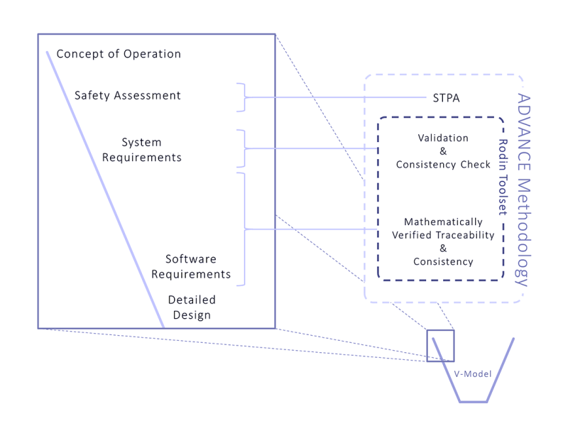
Significant improvements in the methods and tools used for requirements and systems engineering are required in order to move forward. The FP7 ADVANCE project (Advanced Design and Verification Environment for Cyber-physical System Engineering) is a European-wide initiative between industry and academia to lead the future development of high-quality cyber-physical systems. The ADVANCE methodology is built upon the open-source RODIN toolset (Abrial et al., 2010). The methods and tools developed in ADVANCE are open to industry. This article details the techniques that are employed in ADVANCE, including the benefits they can provide and where it is seen as appropriate to practice them, as based on our experiences. Figure 1 below provides an overview of how the ADVANCE methodology integrates with requirements engineering practices as set out in the V-Model.
Smart energy case study
To demonstrate the ADVANCE methodology, a case study is first introduced, which is revisited in later sections to illustrate the techniques through a real-world example. This case study focuses on providing assurance on a control algorithm used in low-voltage (LV) power distribution networks.
The control algorithm is situated at the LV transformer; it influences the voltage level on the LV network by changing the coil ratio of the transformer whilst the transformer is energised. It is complemented by a number of sensor units distributed throughout the LV network, which communicate voltage and current readings back to the algorithm to help it calculate the most suitable transformer setting.
The cyber portions of the system are composed of the control algorithm, the sensor units, and the communication network in-between. The physical portion of the system consists of the LV distribution network, which includes the transformer, individual consumer power demands, and input from consumer photovoltaic generation. There are feedback loops in both directions between the cyber and physical elements; the control algorithm has to be reactive to fluctuating voltages from variations in aggregated consumer demand and photovoltaic input, and the setting it chooses for the transformer will have a knock-on effect on the voltage levels within the network.
One of the main requirements of the control algorithm is that it should maintain the voltage within regulated limits at all consumer points of connection. It should be clear that in order to verify this, it is imperative to consider the behaviour of the physical portion of the system and its interaction with the computational elements.
The ADVANCE Methodology
The ADVANCE methodology is a holistic approach to systems engineering that not only provides guidance for applying formal methods and simulation to systems engineering, from requirements analysis through to the final software product, but also guides safety analysis. In this article, the focus is on the application of the ADVANCE methodology and tools to the requirements engineering phase of the project, but in general, the methodology is also applicable to the system design and software development.
It is broadly accepted that an integral part of requirements specification is to undertake a thorough, all-encompassing, hazard analysis. The ADVANCE method advocates that this should be the innovative System-Theoretic Process Analysis (STPA) developed by N.G. Leveson from experience gained at NASA.
To capture the domain knowledge and environment surrounding the system, which the requirements are validated against, the ADVANCE method recommends the use of physical system modelling languages. One such language, used within the case study and discussed below, is Modelica, which is an open standard. The intention is that these languages succinctly represent the underlying physical environment for the system, which often comprises complex systems of equations.
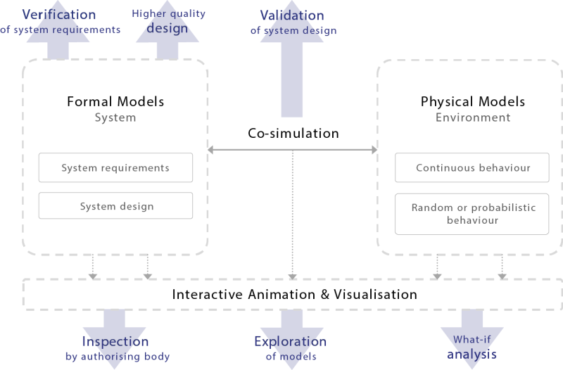
Finally, the requirements of the cyber system are modelled as state machines in a formal language. The combination of mathematical proof within the models and co-simulation with the physical models provides verification and supports validation of the requirements. The use of mathematical proof ensures the verification results are trustworthy and unambiguous. The formal models employ a step-wise approach, which allows for higher-level requirements to be broken down whilst retaining traceability, completeness and consistency. This approach is visualised in Figure 2 below.
Applying this methodology provides the following benefits:
- Insurance that the requirements are unambiguous.
- Identification of gaps or inconsistencies in the system requirements.
- Animation and visualisation of the models to aid in the exploration and validation of the system.
- The ability to conduct ‘what if’ analysis and validate assumptions or changes.
- Automatic identification of scenarios which leave the system in an unforeseen or undesired state.
- Automatic identification of undesirable emergent system behaviour.
Although the approach is valid at any point during the development lifecycle, applying it early on provides the greatest financial benefits as it can highlight issues when it is still feasible to change the requirements or design – in essence, debugging the system requirements. Leaving the identification of these issues until later in the V-model can dramatically increase the cost and effort required for any rectification.
System-Theoretic Process Analysis for Safety Critical Systems
A safety analysis is based on some form of accident model that characterizes the theory of accident causation used to analyse the system. Any accident model relies on a set of assumptions about how accidents can arise, and how the causes that may lead to accidents can propagate, interact, or combine.
As such, it is important to be aware of the main concepts and characteristics of the different accident models when adopting a specific one. Some of the most relevant accident models include:
- Domino Accident Model
- Swiss Cheese Accident Model
- System-Theoretic Accident Model and Processes (STAMP)
The Domino Accident Model is one of earliest proposed accident models. In very brief terms, it proposes a paradigm of chains of events, where, like in a domino effect, each event in the sequence automatically causes the next event, until the final accident. Removing a domino breaks the chain and prevents the accident.
The Swiss Cheese Accident Model distinguishes four consecutive stages: (i) organizational influences, (ii) unsafe supervision, (iii) preconditions for unsafe acts, and (iv) the unsafe acts themselves. The model argues that accidents can be caused by failures starting in any of these stages, in cases where they are not properly handled and they are allowed to propagate to the subsequent stage(s).
The System-Theoretic Accident Model and Processes, STAMP, aims to include a larger diversity of causal factors, including social and organizational structures, human errors, flaws in the requirements and design, and interactions among non-failed components. The “system-theoretic” part of its name reflects the fact that STAMP views safety as a control problem, where accidents result from the interaction of complex dynamic processes.
A safety analysis is either prospective or retrospective. This distinguishes two classes of methods that use accident models:
- Accident analysis methods, to identify the causes of an accident that has already occurred;
- Hazard analysis methods, to identify potential causes of future accidents in a system.
STPA is a hazard analysis method based on the STAMP accident model (Leveson, 2012). Traditional hazard analysis focuses on component failures, but software does not typically fail in the same way. Software most often contributes to accidents by commanding the controlled system into an unsafe state, or by failing to issue required commands. This makes the standard hazard analysis techniques of limited use on software-intensive systems.
STPA addresses this shortfall by treating safety as a control problem, rather than a failure problem. The goal of STPA, which is to create a set of scenarios that can lead to a hazard, is the same as Fault-Tree Analysis (FTA). However, STPA includes a broader set of potential scenarios, including those in which no failures occur but problems arise due to unsafe and unintended interactions between the system components.
STPA is ideally performed early on during a system’s life-cycle; this is reflected by its position at the start of the ADVANCE workflow. Once the high-level architecture and sub-components for the system have been identified, they can be represented as functional control diagrams, which are used to guide the analysis. Performing STPA helps direct – and provide important input into – the modelling process and resulting requirements analysis.
Physical Models
The physical models are used to aid in the validation of system requirements. Typically, these continuous models represent the physical systems (or equivalent plant models) that form the intended environment for the cyber models, and encompass much of the domain knowledge. For example, in the case study, the physical model covers the LV distribution network, which is governed by textbook electrical equations. Here, the domain knowledge of low-voltage power distribution is contained within the electrical equations and topology of the network. Depending on the intended purpose of the system, examples of physical models include the following:
- Vehicles (e.g. aircraft, marine, automotive):
- Fluid dynamics; e.g. flow of medium over vehicle, hydraulic systems.
- Internal mechanical devices; e.g. actuators and sensors.
- Heat dissipation from friction devices; e.g. brakes.
- Communications networks (e.g. Ethernet, wireless, satellite links):
- Signal loss through medium; e.g. weather conditions.
- Waveform interference.
It is clear from these examples that producing accurate models of these physical systems requires substantial domain knowledge and often relies upon complex systems of differential equations.
Although these models can be created directly by identifying the relevant equations from literature, it is often simpler and easier to validate and verify the physical models when using a high-level language to develop them. One such language is Modelica. Modelica allows for multi-domain physical systems to be specified by connecting various blocks together graphically (Fritzson, 2010). These blocks are generic and can represent, for example, a resistive electrical load, rotational mechanics, or a hydraulic servo. Importantly, each block contains variables (discrete and continuous) and their defining equations. Thus, the development of a physical model of the intended system is greatly simplified through the use of a drag-and-drop interface. As an example of this graphical construction, a high-level Modelica model representing the transformer and each of the feeders in the case study is shown in Figure 3.
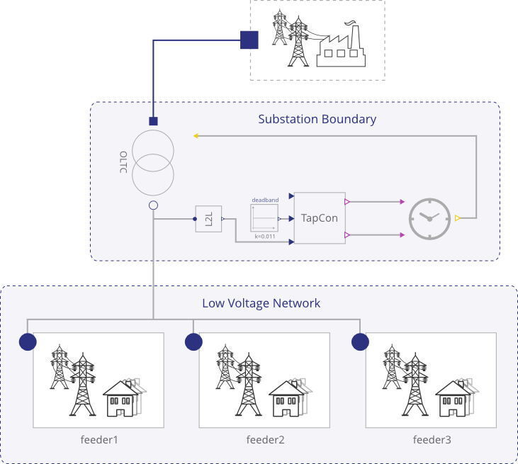
It should be obvious from a cursory inspection what the model represents, in part from the use of descriptive pictures, and also from the names of the objects. This is an important point, as the physical model will be used to aid the validation of requirements, and hence it also needs to be clear exactly what the physical model represents.
Cyber Models and Requirements Verification
In ADVANCE, the cyber elements are modelled using the Event-B language (Abrial, 2010), although it would be possible to use other formal languages in the same approach. The Event-B language was chosen for this work as it is especially good for modelling control systems based on their observable events, as abstract state machines, such as the example in Figure 4 below. Further, Event-B supports modelling functional requirements of these abstract state machines.
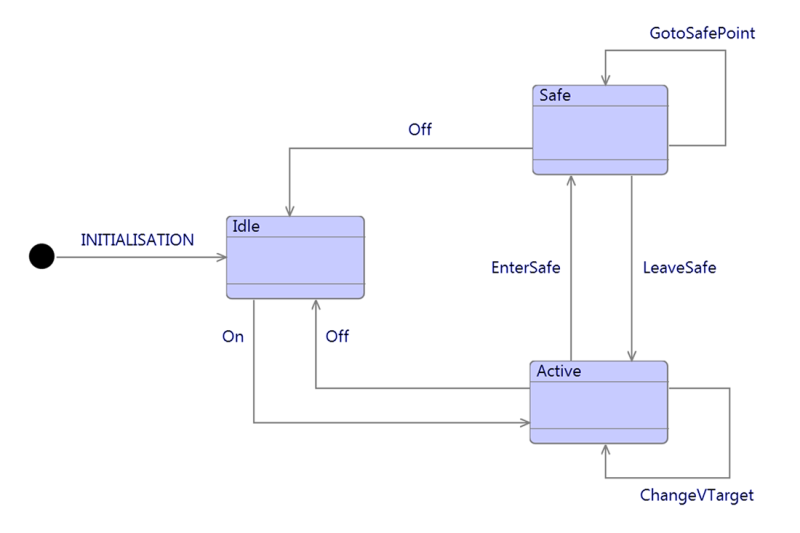
The states and transitions are defined in a mathematically rigorous manner, which means that properties of the model can be analysed – and verified – using automated tools and mathematical proof. Difficultly proving whether the requirements hold in a model can point towards behaviour of the system which either violates the requirements, or is not suitably defined to meet them.
One of the key ideologies behind Event-B is refinement. Modelling starts with abstract state machines, which are gradually refined by introducing additional detail and behaviour in a step-wise fashion. This step-wise refinement aligns well to the methodology of standards such as DO-178C. In addition to separating out the complexity of the models, it allows for an iterative approach to verification. A feedback loop exists between the models and requirements; the models highlight issues in the requirements, which are rectified and then fed back into the model for further examination. Typically a subset of requirements is added in each refinement, so that rather than moving straight from, for example, high-level to low-level requirements in a single step, the approach is more gradual. Because of the mathematical backbone of the models, the consistency between refinements – and hence the consistency and traceability between the high-level and derived requirements – can be proven at each step.
As an example from the case study, when this modelling approach was applied for the control algorithm it demonstrated that:
- The algorithm design could set a target voltage demand beyond that which could be physically achieved by adjusting the coil ratios (i.e. the design did not match the requirements).
- There were input combinations for which the behaviour of the algorithm was not well-defined.
- The mechanism of calculating a new coil ratio in the algorithm could not be fully proven against the requirements; this led to the discovery of a potential behavioural issue in specific circumstances, which was previously unknown and could lead to excessive changing of the coil ratios. This excessive changing would result in reducing the lifetime of the transformer.
Simulation and Validation
It is clear that ensuring that the model is an accurate representation of the system is of upmost importance – there is no use having a verified model if it does not accurately, or sufficiently, represent the features of the system selected for verification. Therefore, rather than relying solely on the engineer to make sure this is the case, simulation and visualisation tools are required. Simulation can be used to step through or execute the model, to ensure it behaves as expected. By linking this simulation to a visualisation, it allows for domain experts to examine and validate the models without having to view any of the formalism. For example, if the system has a control interface, a mock-up of this interface can be created as an interactive visualisation to exactly mimic how the user would interact with the system.
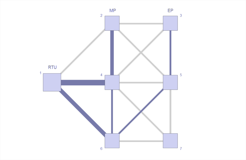
An example of a simple visualisation from the ADVANCE framework is shown in Figure 5 below. This represents the traffic load on a communications network, which is updated dynamically as choices are made during the simulation of a routing protocol model.
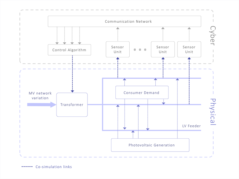
A fundamental pillar of the ADVANCE method is the ability to not only simulate the cyber models in isolation, but also place them in-situ with the physical models and co-simulate the two types of model (Blochwitz et al., 2011). Commands are output to the physical model, and realistic feedback is retrieved, completing the control loop. When applied correctly, this results in helping the systems engineer to validate the system requirements. The co-simulation between the physical and cyber portions of the case study is visualised in Figure 6 below; this is an essential tool in validating the design of the algorithm and envisaging its interaction with the simulated environment.
Conclusions
The ADVANCE methodology has a number of advantages when applied to requirements engineering, but most importantly it supports verification and validation activities. It allows the systems engineer to quickly undertake “what-if” analysis early in the development phase. It provides confidence that, throughout the requirements engineering process, the requirements remain consistent and the low-level requirements satisfy the high-level requirements. The Rodin toolset provides a multitude of open-source solutions to automate the process as much as possible, removing much of the burden of proof from the engineer. There is flexibility around when the approach is applied; due to the abstraction mechanism in the formal models, it can be used to support verification and validation at an initial design stage. For the same reason it can also be used to model and explore a particular sub-system or behavioural attribute of a larger system in isolation.
Our experiences with the methodology point towards significant time and cost savings compared to classical testing and verification approaches, not only due to the early identification of issues, but also due to the time within which the modelling activities succeed in raising the issues. The formal modelling and verification aspects of the methodology provide further advantages over comparative model-in-the-loop approaches. Modelling the control algorithm segment of the system was completed with less than two weeks’ worth of effort from a single experienced engineer. This includes the time performing the proving activities which identified the issues that are mentioned previously. In an additional case study, where the same approach was used to help verify a safety-critical architecture containing a closed system, an undesired scenario was identified after 3 man-months of modelling effort (Reis et al, 2014). The provider of the case study came to the same conclusion with a classical testing approach but after an effort of approximately 12 man-months.
As with all methods, there are some limitations. One of which is a steep learning curve. In part, the use of familiar diagrams, such as state machines, helps to mitigate this. However, this does not negate the need for a reasonable understanding of the underlying principles of the techniques, which can be a challenge for engineers without a mathematical mind-set. Another limitation relates to effective use of the automated analysis, which requires an understanding of how the automated tools function in order to prevent running into performance issues. The final limitation relates to the available documentation; due to the maturity of the methodology, there is a limited supply of high-quality learning material. For example, within traditional software engineering there is the notion of a design pattern (Gamma et al., 1994) and yet, at the time of writing, there are only a handful of identified patterns for ADVANCE. This situation will be improved over time as the benefits of this method become more widely recognised across industry.
From our successful experience in applying the ADVANCE methodology to case studies and industrial problems, it is our view that the methodology is ready for adoption by industry for requirements engineering activities, albeit with specialist support.
Looking beyond the initial requirements engineering stage, there are potential continuations of the ADVANCE workflow that feed into the implementation phase of software development. For example, moving from model-in-the-loop to hardware- and software-in-the-loop methodologies, and also, when the cyber models are in an amenable form, they can be used for automatic code generation.
References
- Abrial, J.-R., 2010. *Modeling in Event-B: system and software engineering*. Cambridge University Press.
- Abrial, J.-R., et al., 2010. *Rodin: an open toolset for modelling and reasoning in Event-B*. International Journal on Software Tools for Technology Transfer. volume 12:447-466.
- Blochwitz, T., et al., 2011. The functional mockup interface for tool independent exchange of simulation models. *Proceedings of 8th Modelica Conference*, pp. 105-114. March 20-22, Dresden, Germany.
- Fritzson, P., 2010. *Principles of object-oriented modeling and simulation with Modelica 2.1*. John Wiley & Sons.
- Gamma, E., Helm, R., Johnson, R. and Vlissides, J., 1994, Design Patterns: *Elements of Reusable Object-Oriented Software*, Addison Wesley.
- Lee, E., 2008, *Cyber Physical Systems: Design Challenges*. University of California, Berkeley Technical Report No. UCB/EECS-2008-8
- Leveson, N.G., 2012, *Engineering a Safer World*, The MIT Press.
- Reis, J., Bicknell, B., Butler, M. and Colley, J., 2014, *Innovative Approach for Requirements Verification of Closed Systems*, in proceedings of ERTS2.

Brett Bicknell is an engineer at Critical Software Technologies and has played a key role in a number of formal methods initiatives, including the FP7 ADVANCE project. His software engineering experience encompasses varying levels of criticality and verification and validation activities. His previous work includes embedded systems, solutions for data acquisition and analysis, and a number of European-funded R&D ventures. He holds a BSc degree in Physics.

Karim Kanso has worked within the field of formal methods and software engineering for many years, on various projects in the domains of transportation and aerospace. He has received a PhD in theoretical computer science, and is actively interested in the question of how requirement engineering can be applied to new disciplines, such as autonomous system engineering? He is currently working on the ADVANCE programme at Critical Software Technologies.

Daniel McLeod has worked on a variety of imaging sensor systems in the Airborne, Land and Naval domains. His previous work includes algorithm development, system design, requirements analysis and verification and project management. He is currently working within the smart energy domain on a Low Voltage monitoring system and a system for automated control of low voltage transformers in response to customer demand and distributed generation.