


1. Introduction
The development of automation plants (e.g., processing facilities in the chemical industry, production facilities in factories, or baggage routing facilities at airports) is a complex planning and engineering task. Typically, such automation plants are highly customized and the entire construction process from the first idea to commissioning takes years, involving many different disciplines like process engineering, physical plant design, mechanics, electronics, and software engineering [1].
In the automation industry the physical architecture of the automation plant is the central engineering artefact regarding the different hardware devices and their interrelationships necessary to perform the technical plant process. Based on the physical architecture of the automation plant, the design of the automation control software takes place. The automation control software acts as the control software of the automation plant and calculates functions, solves equations, and controls the various technical devices of the automation plant (e.g. valves, containers, or conveyor belts). The desired behavior of the automation control software is strongly influenced by strict process requirements, which arise due to the production method, involved materials, and plant components.
Validating whether the automation control software satisfies the process requirements of the entire plant based on the given physical architecture of the automation plant is typically conducted at a late stage in the plant development process, when the physical plant architecture is already designed or even constructed and the technical plant process is defined. However, it is widely acknowledged, that the later in development the control software of a system is validated, the higher the effort for correcting revealed defects will be [2]. This can lead to serious budget overruns, project delays, or to automation plants that do not fulfil their operational purpose [3], which can be detrimental for the overall success of the automation plant development project.
In close cooperation between the Siemens AG, the Technische Universität München, and the University of Duisburg-Essen, we developed a simulation-based approach for the early validation of the requirements for the control software of automation plant [4], [5]. Early in this sense means that validation takes places as soon as information about the technical process and the involved plant components is available, i.e. when conceptualization of the plant is complete, but the plant has not yet been built. As already mentioned above, validating the control software manually by human experts with respect to the plant architecture and the technical plant process is a very time consuming and error prone task. The key idea of the approach is to use simulation during the early stages of the plant development process to automatically assess the impact of the requirements for the automation control software on the technical plant process.
The core characteristics of our approach are the extensive use of models (in the sense of diagrammatic representations) to improve the comprehensibility and traceability of the various engineering artefacts and to systematically cope with the increasing complexity of the automation plants. For the specification of the requirements for the automation control software we use different requirements diagram types proposed by the Syllabus for the IREB CPRE Advanced Module “Requirements Modeling” [6] to foster the extensive automatization of quality assurance tasks as described in the IREB Advanced Level Requirements Modeling Handbook [7]. In this article we demonstrate how requirements modeling according to the IREB Syllabus can be applied.
In Section 2 we introduce the running example of a seawater desalination plant, which is used in this article to demonstrate the core concepts of our approach. In Section 3 we demonstrate how to use requirements modeling according to IREB in order to specify the requirements. Section 4 describes the simulation-based validation of requirements for the control software towards the plant architecture and the technical plant process. Finally, Section 5 concludes the paper.
2. Example “Seawater Desalination Plant”
The concepts introduced in this paper will be explained for a seawater desalination plant. Seawater desalination plants are used to remove salt from seawater in order to produce drinking water. The technology used in this example is based on the principle of reverse osmosis, a separation technology in which water is pumped at high pressure through a membrane that filters out salts. Figure 1 depicts a schematic overview of a typical plant configuration:
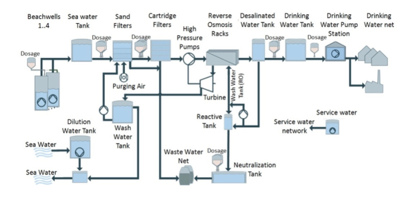
A beach well system is collecting sea water along the coast. The saltwater is then pumped from the beach wells to the sea water tank. It is collected and stored before it will be pretreated and pumped to the high pressure section where the salt will be removed by the actual desalination process. In this article we are focusing on the beach wells only, which have the general purposes:
- Collection of seawater through subsurface intakes, drilled into the seashore
- Filtering seawater through natural sand layers
- Pumping of water from the subsurface intake to the seawater tank
- Controlling of the seawater flow pumped into the seawater tank according to some constraints.
In the automation industry, piping and instrumentation diagrams (P&IDs) are used to describe the architecture of technical plants. The P&ID in Figure 2 shows the main components and their arrangement of one beach well. It is equipped with a control pump to transport water, a bypass control valve to guarantee a sufficient flow delivered by the pump, and a discharge valve through which water is advanced to the seawater tank.
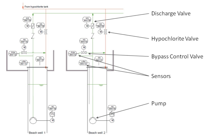
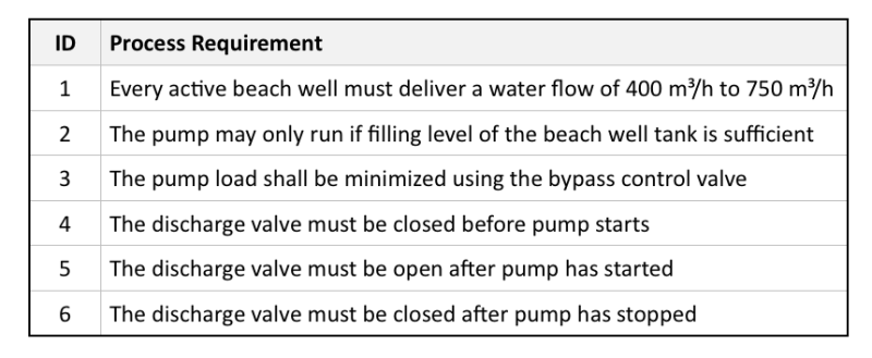
The software operating the beach wells is controlling these actuators under consideration of the additional sensor values. This software must ensure that these actuators are controlled in a coordinated fashion in order to optimize the desalination process and to avoid damage to the plant (e.g., when the beach well pumps run dry). Before implementing the software process requirements must be collected in order to define the proper behavior of the system in accordance with the physical process itself. Table 1 shows an excerpt of such process requirements for a beach well.
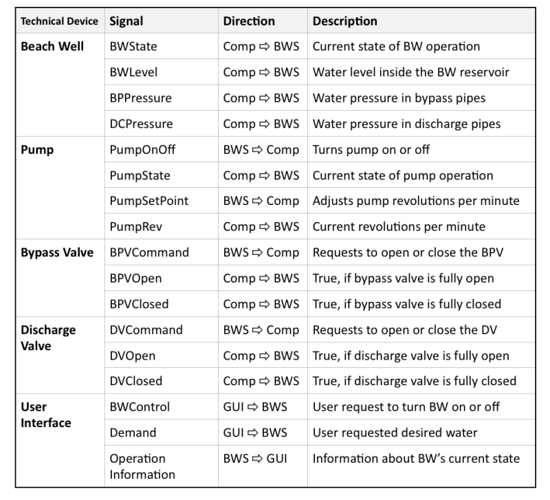
To control the technical process, it is necessary to exchange signals between the beach well software and the beach well actors and sensors as well as with the operator. An excerpt is shown in Table 2. We are distinguishing three types of signals: Signals from the beach well and its components (Comp ⇨ BWS in Table 2) deliver information about the state of the beach well, which are used by the beach well software to control and coordinate the beach well (BWS ⇨ Comp in Table 2), depending on requests from the user (GUI ⇨ BWS in Table 2).
3. Requirements Modeling in the Engineering of Automation Plants
The IREB Handbook for Requirements Modeling [7] describes the various benefits of a diagrammatical specification of requirements, e.g. with respect to the management of complexity, improved comprehensibility and the potential to automate particular quality assurance tasks. In this section, we demonstrate how selected diagram types from the IREB Advanced Level Syllabus “Requirement Modeling” can be applied in order to specify requirements for the control software of automation plants. We illustrate this by the example of the seawater desalination plant described in Section 2 and also pinpoint the tools that can be used.
3.1. Overview
The process requirements from Table 2 govern the physical filtration process that the desalination plant must carry out. In consequence, the control software must control the beach wells such that these process requirements are fulfilled. In the following, we give some insights in the requirements models for a beach well control software based on the requirements views proposed in the IREB Handbook for Requirements Modeling [7]. We will see that such a requirement specification enables an automated requirements validation by co-simulating the beach well control software and the beach well components the beach well software is meant to control in accordance with the process requirements.
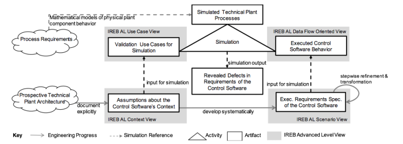
As proposed in [4], [5], we explicitly document the assumptions about the technical plant architecture by means of context models (see Section 3.2) using UML modeling tools. Based on these context models, validation use cases can be defined. Validation use cases describe the operational scenarios of the beach well software that lead to satisfaction of the process requirements and can be used to document safe behavior of the beach well software in case of malfunction [8]. Validation use cases are documented using simple templates (see Section 3.3.1) and a formalized representation of the use cases can be systematically derived, which serves as an executable requirements specification for the co-simulation process (see Section 3.3.3). Afterwards, the developer configures a simulation tool based on the technical processes that are conducted in the plant (see Section 3.2.4), so that the behavior of the control software can be executed (see Section 4) and automatically checked against the validation use cases. The output of the simulation is a set of incorrect and incomplete behavioral requirements of the automation control software. Figure 3 gives an overview of our approach.
3.2. Context Modeling
Our aim is to conduct the validation of the requirements for the control software at the earliest possible point during the development process, i.e. when assumptions about the intended behavior of the prospective technical plant architecture can be made. In requirements engineering, such system properties are often documented in three distinct perspectives focusing on static-structural, functional, or behavioral properties of the system [9]. We adopt these perspectives to document assumptions about the technical plant architecture. Specifically, we employ a number of diagrammatic representations, which we call operational context models. Chapter 2 in the IREB Advanced Level Requirements Modeling Handbook [7] proposes modeling the context of a system under development mainly by means of static-structural models. Yet, as outlined in Section 2.3 of the Requirements Modeling Handbook [7], context information can be found in many different artifacts and could, for example, consider functional interaction of systems, or the behavior of external systems as well. We therefore use structural operational context models (see Section 3.2.1), functional operational context models (see Section 3.2.2), and behavioral operational context models (see Section 3.2.3). To be able to use the context models for simulation, we additionally provide a view on the continuous behavior of the technical plant functions (see Section 3.2.4).
All context models are represented by regular UML/SysML diagrams, which express the assumptions about the technical plant (i.e. the physical plant components) as opposed to the system under development itself (i.e. the beach well control software). The context models are a vehicle to document and refine our understanding about the technical plant architecture that “surrounds” the control software. In the automation industry, hardware components are usually pre-constructed and the control software is created during late stages of development for the purpose of orchestrating the functional interplay of technical components. This is not necessarily the case in other domains. Nevertheless, modeling the context of the control software is applicable at any point during development, even if the automation plant is not yet completely defined or constructed. As long as the technical plant architecture, including its components, interfaces, signals, functions, and quality properties, are constructed as it is assumed in these context models, and as long as the system is correctly constructed from its functional requirements (see Section 3.3), the validation results (see Section 4) will adequately reflect whether or not the beach well control software meets the process requirements.
Context models can be created using regular UML tools, such as Eclipse UML2 [14], Sparx System’s Enterprise Architect [15], or IBM Rational Rhapsody [16]. In the following, we illustrate the three types of operational context models. We used these context models to document the assumptions about the context of the beach well control software.
3.2.1. Structural Operational Context Models: Documenting Assumptions about the Physical Structure Surrounding the Beach Well Control Software
The structural operational context model documents structural characteristics of the beach well control software, the beach well’s physical components, and the information exchanged between them and the beach well control software. This includes interfaces and interactions between human users and control software of other plant components.
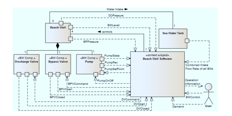
Figure 4 shows the structural operational context of the beach well. Structural operational context models can be depicted using regular UML class diagrams using the EA’s built-in facilities as well. The beach well is annotated with the stereotype <
3.2.2. Functional Operational Context Models: Documenting Assumptions about the Functional Interplay Between the Beach Well Control Software and the Context
The functional operational context model documents the functional interplay of the beach well control software and the functionality of the physical components in the context (see Section 3.2.1). This allows adopting a service-oriented view on the functionality as only functions influencing one another are depicted in the diagram. Furthermore, functional interaction can be analyzed in subsequent validation steps by assigning concrete values to the signals from the structural operational context model. Figure 5 depicts the functional operational context model of the beach well software functions and the beach well component functions.
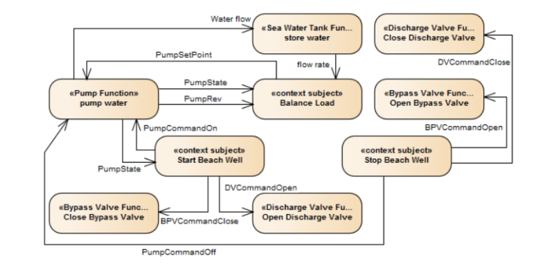
As can be seen in Figure 5, the beach well software offers three externally visible functions through which the beach well components are controlled. These are documented using regular rounded-edge rectangles, which are customarily used to depict UML actions or UML activities and bear the stereotype << context subject >>. The beach well provides the functions: “start beach well”, “stop beach well”, and “balance load”. The signals from the structural operational context model of the beach well software (see Figure 4 and Table 2) have been assigned with concrete values: The function “start beach well” shall only close the bypass valve and open the discharge valve if the pump has built up sufficient water pressure, such that water can flow into the seawater tank. Similarly, the function “stop beach well” turns the pump off, opens the bypass valve, and closes the discharge valve when water pressure is less than 20% of the maximum pressure. Furthermore, it can be seen that all three beach well control software functions make use of functions that can are located in the operational context of the automation control software: For example, in order to start the beach well, the bypass valve and the discharge valve need to be closed, which is done by toggling the available functions of the beach well components from Figure 4.
3.2.3. Behavioral Operational Context Models: Documenting Assumptions about the State-Space of the Functions and Components Surrounding the Beach Well Control Software
The behavioral operational context model documents the externally observable states of the physical plant components. In this sense, internal states of the plant components or the functional interplay are abstracted and only the states relevant to the automation control software are depicted. Transitions between these states are triggered by values of the signals from the functional operational context (see Section 3.2.2).
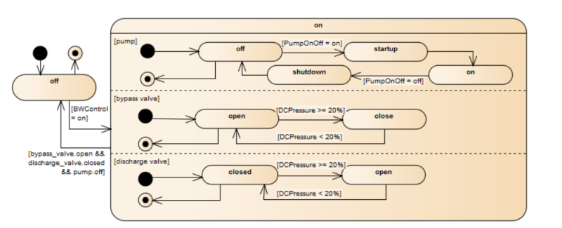
Figure 6 shows the example of the behavioral operational context relevant for the beach well’s control software. The diagram in Figure 6 is a regular UML state machine diagram and depicts the externally observable states of the beach well components from the structural operational context (i.e. the bypass valve, the discharge valve, and the pump) of the entire beach well (see Section 3.2.1). Concurrent sub-states are used to separate the components from the structural operational context, as their respective states are mutually discrete, but state changes within components can of course occur concurrently. The guards on the transitions are conditions specified in the functional operational context model (see Section 3.2.2) with regard to the beach well function “start beach well”. Both bypass valve and discharge valve can be either open or closed, depending on the water pressure level (see Figure 5). The pump can be off, on, or in an intermediate state (startup or shutdown). The transition between “pump.startup” and “pump.on” does not have a guard. This indicates that, although there is an event that triggers the transition, the condition for this event is private to the pump and not externally visible. In other words, the beach well software can only observe the states but has no influence on when this transition occurs.
3.2.4. Modeling the Continuous Behavior of the Technical Plant Functions
The IREB Handbook on Requirements Modeling [7] provides diagrammatical representations to describe the operational context based on discrete events. For the purpose of simulative validation, we need a realistic description of the assumed plant behavior, which is usually characterized by continuous signals. Therefore, we additionally provide a model to specify the technical plant behavior by describing the physical plant components by mathematical models (typically differential/algebraic sets of equations). In the automation industry, these mathematical models are often synthesized from component libraries containing mathematical behavior models for generic physical plant components. The relevant configuration parameters (e.g. height of tanks, length of pipes, etc.) of each component can be modified for different plant instances. Figure 7 shows how a technical plant architecture model with a beach well tank, a pump, a discharge valve, and a seawater tank is transformed into a continuous behavior model.
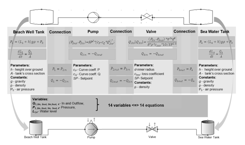
The upper section of Figure 7 depicts the relevant excerpt of the technical plant architecture. Alongside the pump and the discharge valve from the structural operational context model (see Figure 4), which are controlled by the beach well software, the beach well intake tank and the seawater tank are depicted. All components can be found in the piping and installation diagram (P&ID, see Section 2). The middle section of Figure 7 shows the differential equations for flow, filling level, and pressure for both the beach well tank and the seawater tank. The behavior of the pump and the discharge valve is described by equations for flow and pressure. Since the four components are connected by three connections (which in a commissioned plant may correspond to water-bearing pipes), six additional equations are necessary to describe the flow balance in the physical pipes and the pressure potential at the connection points. In total, this system contains 14 equations and 14 variables.
Once the relevant physical plant components are identified by means of the structural operational context model and once the equations representing their behavior have been compiled, the simulation tool can be configured, as indicated by the rounded arrows on the left and right sides of Figure 7. In our example, we use the tool CoSMOS [11], which uses icons similar to the P&ID (see the lower section of Figure 7). Using this tool, the plant behavior can be simulated by solving the resulting differential algebraic equations system. Other tools such as Aspen Plus [17], Simulink [18], or Modelica [19] can be used for this purpose as well.
3.3. Requirements Modeling in the Dynamic Views
The focus of requirements for automation systems is on desired system functionality. In this particular case, information structure diagrams which can be used to describe data and their relations play a minor role. Therefore, we focus on dynamic views of requirements modeling proposed in [7] including use case modeling, scenario modeling, function modeling by use of data flow diagrams, and state-oriented modeling of behavior.
3.3.1. Use Case Modeling
Based on the context models, validation use cases can be developed for every function of the automation control. Validation use cases comprise a number of scenarios, which are sequential steps of interaction between the automation control software and the physical plant components [8]. They contain one success scenario (i.e. the sequence of steps leading to the desired post-condition), a number of alternative scenarios (i.e. alternative interactions leading to the same post-condition), and a number of exception scenarios (i.e. undesirable interactions, which violate the post-condition).
The validation use cases reference the externally visible states of the physical plant components from the behavioral operational context models, which serve as pre- and post-conditions for performing the function of the automation control software. These are used as acceptance criteria under which the behavior of the automation control software is considered valid with regard to the process requirements. Table 3 shows the validation use case “Start Beach Well” of the beach well.
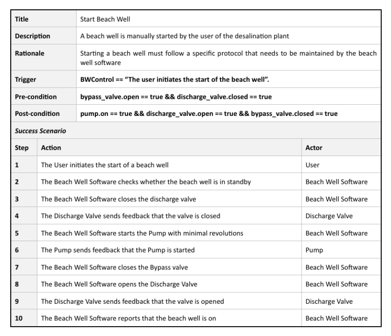
The purpose of this validation use case is to operationalize the requirements from Table 1. Process requirements for a beach well, specifically requirements 2, 4, and 5. As shown, we document validation use cases with templates that contain the essential information about this use case in accordance with [8]. For brevity, in the example only the main scenario is shown and the alternative and exception scenarios have been truncated.
Requirements 4 and 5 from Table 1 are documented as pre- and post-conditions of the validation use case. The concrete conditions have been extracted from the behavioral operational context model (printed in bold in Table 3). The trigger of this validation use case relates to a signal from the user interface to the beach well software, depicted in the structural operational context model. Since the process requirements 2, 4, and 5 imply a certain sequence of valve actuation and minimal tank filling level, the beach well software must perform several sequential steps, documented in the success scenario.
3.3.2. Scenario Modeling
Scenario modeling provides a way to detail and formalize the specified use cases and to connect them with the context models. To this end, every scenario of each validation use case is refined into a Message Sequence Chart (MSC) [10]. MSCs describe the informal steps from the scenarios by means of formal messages between the automation control software and the physical plant components. Figure 8 shows the formalization of the success scenario from Table 3. MSCs are one specific notation for modeling scenarios. An alternative notation is, for example, provided by UML/SysML Sequence Diagrams.
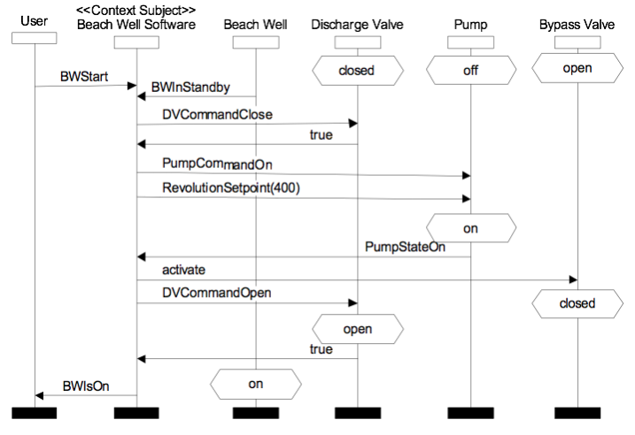
In this formal representation, the interface information from the structural operational context model (see Figure 4) is transferred to a sequence of formal messages. These messages trigger transitions from one state to another. These states correspond to the externally observable states of the physical plant components from the behavioral operational context model (see Figure 6).
3.3.3. Requirements Modeling with Data Flow Diagrams
The core elements of the models from the dynamic view are the functions that should be provided by the respective system. These were identified in the functional operational context diagram (see Section 3.2.2). These functions are now specified in a more detail by using data-flow models.
As counterpart to the technical plant behavior, we model the functionality of the control software to validate the behavior that emerges from the interaction between the control software and the technical plant it controls. Therefore, we structure the functionality of the automation control software by means of functions [12]. A function summarizes a set of requirements concerning the user interaction and formalizes them by means of an executable behavior description. Figure 9 shows the two functions we defined for the beach well software.
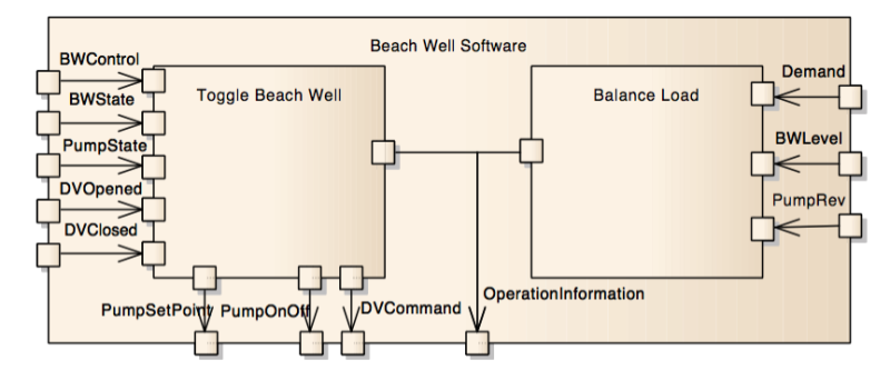
For the specification of the behavior described by the validation use cases, we define two functions: “toggle beach well” and the “balance load”. Each of these two functions handles a subset of the input and output signals of the control software that are specified in the structural operational context model (see Figure 4). In this case, both functions are independent from each other. In an automation plant with a higher degree of automation, for example, if the function “balance load” may automatically start or stop additional beach wells by activating the function “toggle beach well”, it is necessary to add internal channels that model the communication between functions [13].
3.3.4. State-oriented Modeling of Behavioral Requirements
Functions can be decomposed into further sub-functions or their behavior must be specified in terms of an executable behavior description (e.g. a state machine, a table specification, or a code snippet). The reason for this is that we want to use the system specification in a simulation to execute the scenarios from the validation use cases. Figure 10 shows a state machine that describes the behavior of the “toggle beach well” function, which can be used to execute the success scenario from Figure 8.
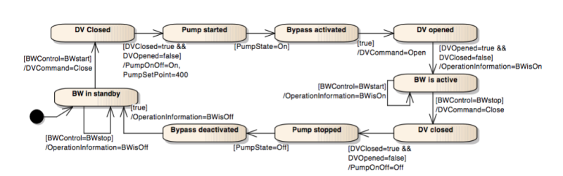
The state machine describes the behavior of the “toggle beach well” function by a sequence of state transitions. The state transitions are triggered by conditions that reference the inputs of the corresponding function (e.g., BWControl=BWstart). Each transition specifies some output values that must result when the transition occurs (e.g., DVCommand=Close). In this way, we define the desired executable behavior of each function defined in the data flow diagram in Figure 9.
Automating Quality Assurance based on Requirement Models
After the validation use cases are documented and their scenarios formalized, a simulation tool can be configured (e.g. CoSMOS [11]). The general idea is to try to reenact the validation use cases in a simulation of the automation control software and the technical plant architecture. For this purpose, the technical plant behavior and the control software behavior must be modeled in an executable way (see Sections 3.2.4 and 3.3.4). Furthermore, both must be coupled in a simulative process, which executes the validation use cases.
The simulation tool concurrently executes the behavior models of the control software and the technical plant. The validation use cases and their associated scenarios are used as input for the simulation. If the simulation tool is able to execute the scenarios and the externally observable states from the behavioral operational context models match the final states of the physical plant components by the end of the simulation, the requirements specification is valid with regard to that use case. If the simulation tool is unable to execute the validation scenario and/or the post-conditions do not match the assumed externally observable states of the physical components, this is an indication that there is a defect. This defect may comprise incorrect or incomplete automation control software requirements, incorrect assumptions in the context models, or erroneously configured simulation parameters.
We implemented the approach using the academic tool AutoFOCUS 3 [20] to develop the context models, the validation use cases, and the executable control software specification. We used the industrial tool CoSMOS to create an executable model of the technical plant process. To perform the validation process, we coupled the tools in the following way (see Figure 11).
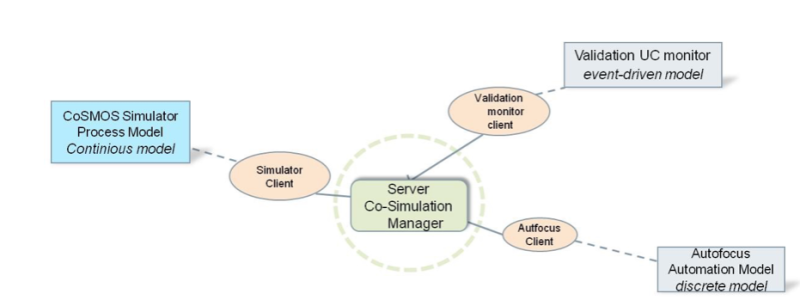
CoSMOS offers an open client-server co-simulation architecture. In this architecture, the co-simulation server orchestrates the interactions between simulation clients. Therefore, we implemented client instances for the AutoFocus3 simulation of the control software, and for the CoSMOS simulation of the technical process. The goal of the simulation is to reenact specified validation scenarios. For this purpose, the co-simulation server performs at every predefined sampling point one time step in the control software simulation, which is a discrete model. This means, the control software is evaluated only on predefined time steps. The output then serves as input for the continuous model of the technical plant simulation, which then covers the time between two steps of the discrete sampling points.
On top of this coupled simulation process, there is a third component also implemented as a simulation client called validation use case monitor. We feed this validation use case monitor component with the validation use case scenarios from Section 3.3.2. Technically, the validation use cases are translated to an XML file by expressing each scenario step as a simple condition/action rule (see left side of Figure 12).
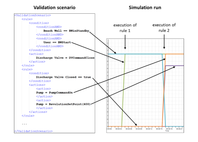
This event-driven model monitors the simulation process and injects messages according to specified condition/action rules. The validation use case monitor is initialized with the first rule (i.e. scenario step) marked as “active”. When the condition of this active rule is fulfilled by the running simulation, the corresponding action injects messages to the simulation and the following rule within the validation use case monitor is marked as “active”. After the last rule (i.e. the last scenario step) has been processed, the validation use case monitor reports that the validation use case scenario has been reenacted by the simulation. If a currently active rule is not processed for a certain duration (timeout), then the validation use case monitor reports that the validation use case scenario could not be reenacted and therefore that the validation has failed. Figure 12 shows a visualization of the technical plant behavior over time that reflects the desired behavior as specified by the success scenario of validation use case “Start Beach Well”.
Conclusion
In this article we presented an approach for the early validation of automation control software based on the specified requirements for the control software. An important pillar of the technique is the specification of requirements according to different requirements views proposed in the IREB Advanced Level Syllabus “Requirements Modeling”. The approach relies on context modeling in order to precisely describe the assumptions concerning the relevant parts of the physical plant architecture, use case diagrams and scenario modeling as well as functional and behavioral requirements diagrams. In order to perform simulation-based validation, the automation plant behavior and the control software behavior must be modeled in an executable way and need to be coupled in a simulative process, which executes the validation use cases in order to find defects in the requirements for the automation control software. Even though our approach aims at the validation of requirements for automation control software, this approach can be widely used to validate software of technical systems with complex technical and physical constraints. This applies, in particular, to systems in which software controls technical processes, which are immutable and in which valid assumptions about the physical design of the system can be made early in the development process.
Acknowledgement
The work reported in this article was partially funded by the German Federal Ministry of Education and Research under grant number 01IS12005 (SPES 2020_XTCore).
References
- [1] U. Löwen, R. Bertsch, B. Böhm, et a.: Systematization of the Engineering in Automation Plants. In: Automatisierungstechnische Praxis 4, pp. 54-61 (2005)
- [2] K.-H. Möller: Ausgangsdaten für Qualitätsmetriken – Eine Fundgrube für Analysen. In: Software-Metriken für die Praxis, Springer, pp. 105-116, 1996.
- [3] B. W. Boehm: Software Engineering Economics. Prentice Hall, 1981.
- [4] V. Brandstetter, A. Froese, B. Tenbergen, A. Vogelsang, J. Wehrstedt, T. Weyer: Early Validation of Control Software for Automation Plants on the Example of a Seawater Desalination Plant. In: Proc. of the CAiSE 2015 Forum at the 27th International Conference on Advanced Information Systems Engineering (CAiSE 2015 Forum), 2015
- [5] V. Brandstetter, A. Froese, B. Tenbergen, A. Vogelsang, J. Wehrstedt, T. Weyer: Early Validation of Automation Plant Control Software using Simulation Based on Assumption Modeling and Validation Use Cases. In: Complex Systems Informatics and Modeling Quarterly, Issue 4, pp. 50-65, (2015).
- [6] L. Baumann, T. Cziharz, C. Hood, P. Hruschka, U. Meseberg, S. Queins, A. Strasser, T. Weyer: Requirements Modeling, Advanced Level Syllabus, Version 2.0, available at https://www.ireb.org/en/downloads/tag:al-modeling#top (2015).
- [7] T. Cziharz, P. Hruschka, S. Queins, T. Weyer: Handbook of Requirements Modeling IREB Standard, Version 1.1, available at https://www.ireb.org/en/downloads/tag:handbook (2015)
- [8] A. Cockburn, Writing effective use cases, 16th ed. Boston: Addison-Wesley, 2006.
- [9] A. M. Davis, Software requirements: Objects, functions, and states, 4th ed. Englewood Cliffs, NJ: PTR Prentice Hall, 1993.
- [10] ITU-T Z.120: Formal description techniques – Message Sequence Chart, 2011.
- [11] T. Schenk, A. Gilg, M. Mühlbauer, R. Rosen, J.C. Wehrstedt: Architecture for modeling and simulation of tech-nical systems along their lifecycle. Computer Visual Science 17, 2015, pp. 167-183.
- [12] A. Vogelsang, S. Eder, G. Hackenberg, M. Junker, and S. Teufl, “Supporting Concurrent Development of Requirements and Architecture - A Model-based Approach,” in Proc. of MODELSWARD’14, 2014, pp. 587–595.
- [13] A. Vogelsang, H. Femmer, and C. Winkler, “Systematic Elicitation of Mode Models for Multifunctional Systems,” in Proc. of 23rd IEEE International Requirements Engineering Conference (RE’15), 2015.
Tool References
- [14] Eclipse Model Development Tools and UML2. Available at: http://www.eclipse.org/modeling/mdt/?project=uml2
- [15] Sparx Systems Enterprise Architect. Available at: http://www.sparxsystems.com.au/products/ea/
- [16] IBM Rational Rhapsody. Available at: http://www-03.ibm.com/software/products/de/ratirhapfami
- [17] aspentech Aspen Plus. Available at: http://www.aspentech.com/products/engineering/aspen-plus/
- [18] The Mathworks Inc. Simulink. Available at: http://www.mathworks.com/products/simulink/
- [19] Modelica Association Modelica. Available at: https://www.modelica.org/
- [20] Fortiss AutoFOCUS 3. Available at: http://af3.fortiss.org/

Bastian Tenbergen is an Assistant Professor for Computer Science at the State University of New York at Oswego. He has co-authored articles and contributed to several books in the area of Software Engineering. Bastian’s main research focus is on Model-Based Requirements Engineering, Context Analysis, and Safety of Embedded and Cyber-Physical Systems. He has many years of project and consulting experience and has worked closely with industry.

Andreas Vogelsang is a post-doc researcher in the software & systems engineering group at the Technical University of Munich. He works on model-based requirements engineering and participated in several research collaborations with industrial partners especially from the automotive industry. His research published was published in relevant international conferences like RE, REFSQ, or ICSE.

Thorsten Weyer is a research group leader at the University of Duisburg-Essen. He has been a member of organization committees, program committees and reviewer for scientific conferences and journals. Thorsten gives regular lectures at the University and is an experienced conference speaker. He has also held several leading positions in research projects and technology transfer projects. He is member of the IREB council and head of the IREB working group Requirements Modeling.

Andreas Froese works as a research assistant in the working group Software Systems Engineering (Prof. Dr. Klaus Pohl) at the University of Duisburg-Essen. He worked in several research projects where he was able to expand his knowledge in the domain of Requirements Engineering for software-intensive Embedded Systems, as well as in those of model-based Context Analysis and context-based Quality Assurance.

Jan Christoph Wehrstedt works as a mathematician at the Technology Field Automation & Control at Siemens Corporate Technology. Currently he is Senior Key Expert for Efficient Simulation Driven System Development. He is the project manager of several business (Siemens internal) and public funded projects dealing with the integration of simulation and modeling approaches towards a simulation based engineering of technical systems and plants and it’s embedding into PLM lifecycle and tools.

Veronika Brandstetter is a mathematician in the Technology Field Automation & Control at Siemens Corporate Technology. She is developing methods for seamless engineering and improved operation of technical systems based on simulation. Recently, she focused on simulation based design for manufacturing technologies. She has been working in various Siemens internal research projects as well as in publicly funded projects also managing part of them in different groups within the Technology Field.