Gildas Premel-Cabic
Discovering System Requirements through SysML
An application of the IREB Handbook of Requirements Modeling
For Business Analysts/Requirement Engineers/System Analysts, the greatest innovation brought by the Systems Modeling Language (SysML) is the introduction of 1) the requirement as a modeling element type, 2) the requirement relationships and 3) the requirement diagram. Requirement specification with SysML has become a topic of articles such as [REF01], [REF02] and books [REF03], as well as the IREB Requirements Modeling Handbook [REF04] which considers how to precisely model requirements with SysML diagrams. Yet the manual does not show these SysML’s requirement items in action as they do not model the actual content of the requirement; this still remains textually specified. This article illustrates the application to a study case of the IREB manual including the use of the SysML requirement diagram.
1 Requirement, requirement model & requirement diagram
The SysML’s requirement type element serves as a basis to specify text-based requirements. In fact, its true value relies on the ability to link it to many SysML modeling element types: requirement but also block, actor, use case, activity, interaction, state machine, etc. The requirements and the requirement relationships form the requirement model which is fully depicted with the SysML requirement diagram i.
With SysML, System Analysts can relate the individual text-based system requirements to the elements that model the system and thus show where the requirements originate from. Surprisingly, this traceability capacity is rarely shown in articles and books dealing with requirement modeling.
2 Case study
The case study is inspired by the Network Pump®. Information about the device is taken from documents [REF05], [REF06] and [REF07]. The Pump enables software applications operating on a lower security network to pass information to software applications onto a higher security level network automatically, in a secure and reliable manner. These applications are later denoted “Low App” and “High App” in the Pump’s SysML model ii.
In this paper, the SysML model does not attempt to depict exactly the Pump. It rather illustrates how SysML can be used in the analysis phase of a system which is seen as a black box. The outcome of the phase is a comprehensive and consistent set of requirements that the system must fulfill.
3 SysML models initiated during the requirement elicitation phase
3.1 Requirement models
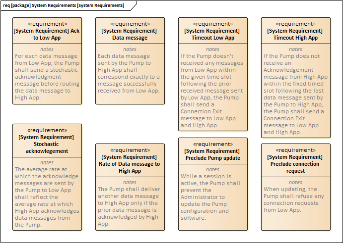
The business and user needs, business rules, system performances and constraints found out during the elicitation phase are modeled as SysML requirements, each defined by an identifier and a textual specification:
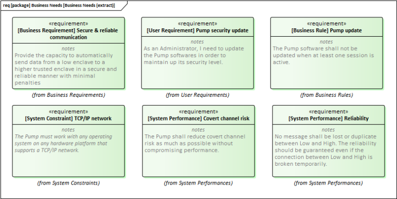
The SysML requirement diagram is the « place » where requirements can be related. SysML offers 7 requirement relationships [REF01]. The semantics of these relations is not controlled: a requirement can be related to another requirement by any type of requirement relationship. However, links between requirements enforce the consistency of the requirement set:
3.2. Context models
The stakeholders of the Pump can be depicted in a SysML block definition diagram (BDD):

The operational environment of the Pump is depicted by a block definition diagram together with an internal block diagram (IBD):
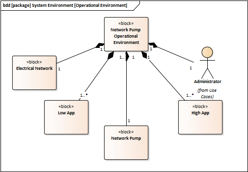
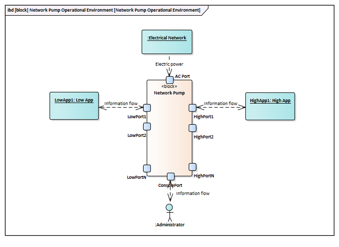
The BDD shows the structural elements of the system operational environment i.e. who (person) and what (system) can interfere with the Pump. Cardinalities indicate the possible configurations of the operational environment (i.e. how many applications can be connected to the Pump). The IBD shows on a concrete environment model what can flow into and out of the Pump through its interfaces.
4 SysML models initiated during the analysis phase
4.1 Use case model
Given the findings obtained during the elicitation phase, use cases come first when analysing a system. For the Pump, two use cases are identified:
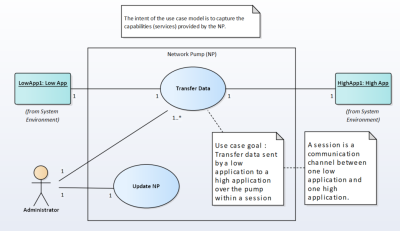
At the system level, the intent of the use case model is to capture the capabilities (services) the Pump must provide in order to fulfill the requirements of the stakeholders. Among these stakeholders are the actors interacting with the Pump.
The “Transfer Data” use case is triggered by a low application (primary actor) in order to send data to a high application (secondary/supporting actor) over the Pump in the context of a session. Multiplicities on the association ends mean [REF03] that:
- Data are passed from one low application to one high application (actor end)
- Low App and High App participate in only one session (use case end)
- The Administrator can act upon the course of the sessions.
The “Update NP” use case is triggered by the Administrator. This use case develops the user stories “Pump configuration update” and “Pump security update”.
4.2 Modeling the “Transfer data” use case
Generally, use cases are described using a structured, text-based specification defining: 1) the necessary conditions that must hold to start the use case (trigger and preconditions), 2) the outcomes of the use case (postconditions, minimal guarantees), 3) the steps iii of the scenarios (main, alternatives, exceptions) [REF08].
In practice, the main difficulty is to efficiently describe the combinations of the steps forming the various scenarios contained in a use case. The issue can be overcome by a modeling approach.
In a Model-Based Requirements Engineering approach, each step of a use case can be modeled by a SysML activity, an interaction or a state and the scenarios contained in a use case can be captured in an activity or a state machine. Modelers must make choices iv, one criterion being the nature of the use case (is it device-driven or human-driven?).
Transferring data from Low App to High App over the Pump is basically an automatic, message-driven process triggered by Low App. Thus, a relevant choice is to model the steps of the transfer data use case by a state and to capture the use case dynamics in a single state machine:
States are time slots where preconditions hold or interactions are performed:
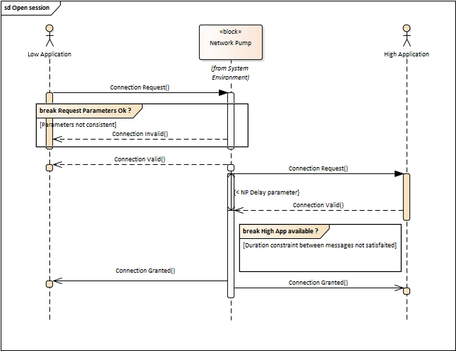
Transitions between states are triggered by message reception events. Each scenario is modeled by a specific set of transitions between states, leading to one final state from the initial pseudo-state.
Step (state) 2 is repeated for each data message sent by Low App to the Pump. The state is left:
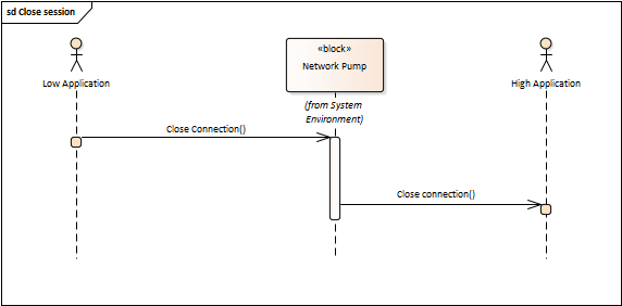
- If the Pump receives a Close Connection message from Low App (use case main scenario)
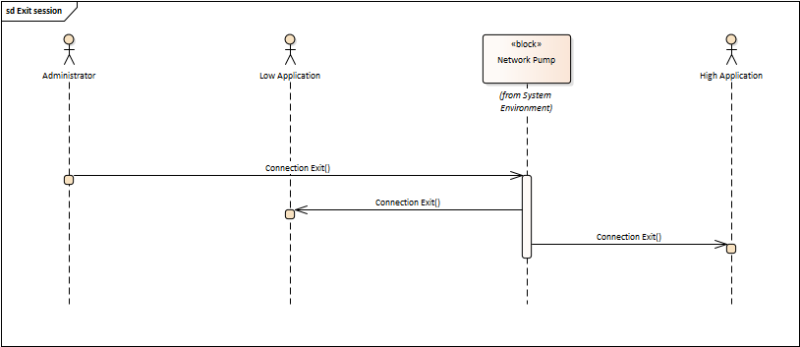
- If the Pump receives a Connection Exit message from the Administrator (alternate scenario)
- Upon Low App or High App timeout events (exception scenarios)
5 Specifying textual system requirements from models
Specifying requirements with models does not eliminate the need for text-based requirements:
- Models can still be ambiguous. “Customers” of the models must have a basic knowledge of SysML, be informed about the modeling methodology used (if it exists) and the intention of each model to get the appropriate understanding of the overall system model.
- Models can still be incomplete. Not everything can be efficiently expressed with models. From the business rule “Pump update” [figure 1], it follows that the use cases “Transfer Data” and “Update NP” must not run simultaneously. Modeling conflicts between use cases is tricky. This situation is efficiently specified by means of the text-based requirements “Preclude connection request” and “Preclude Pump update”.
- Models mainly highlight the functional aspects of the modeled system.
Textual system requirements derived from models should supplement, where necessary, what the models themselves state. They should include condition and/or quality (performance) items [REF10], [REF11]:
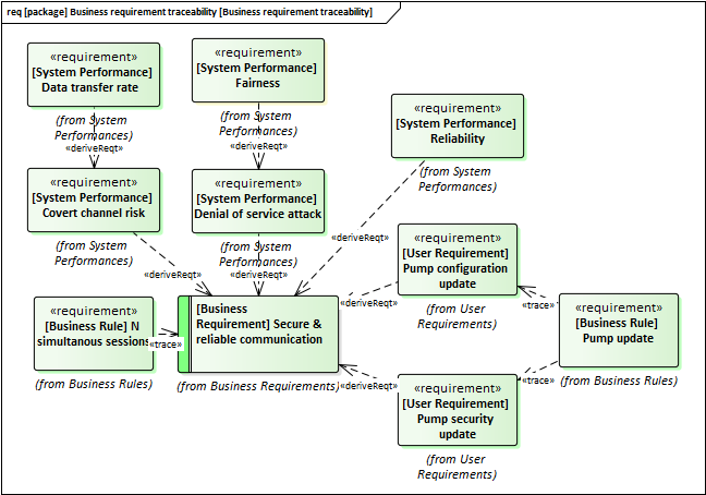
6 Requirement traceability
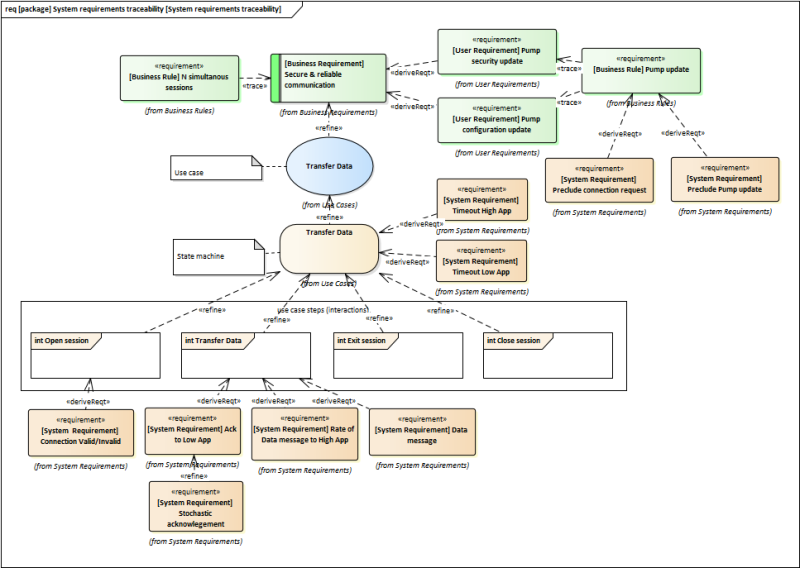
The SysML requirement diagram is flexible. Any model element that has a name can be a node on it; nodes can be related by the requirement relationships. During the system analysis phase, the derive, refine and trace relationships are appropriate to link the model elements. In fact, the semantics of the relationships does not really matter: the resulting network aims to trace the system requirements back to the business needs through the model elements resulting from the system analysis:
7 Conclusion
The Network Pump provides a relevant case study to illustrate how SysML can be used by System Analysts to discover, specify and relate the textual system requirements to their sources. System requirements do not only derive from parent requirements but also from models which, in turn, are sources of requirements.
So far, we have not mentioned the parametric diagram, introduced by SysML in addition to the requirement diagram. The parametric diagram works together with the SysML constraint block. The intent is to build and run models that capture constraints of the modeled system in order to perform engineering analyses, such as trade-off analysis [REF03]. These modeling elements do not really help System Analysts to discover and specify requirements, even non-functional ones. These performance (quality) requirements need to be discovered during the elicitation phase [REF12].
8 References
- [REF01] P. Roques “Modeling Requirements with SysML”, 2015. Online at: re-magazine.ireb.org/articles/modeling-requirements-with-sysml
- [REF02] N. Belloir, J.M. Bruel, R. Faudou « Modélisation des exigences en UML/SysML »
- [REF03] S. Friedenthal, A. Moore, R. Steiner “A practical guide to SysML”, 2nd edition
- [REF04] T. Cziharz, P. Hruschka, S. Queins, T. Weyer “Handbook of Requirements Modeling IREB Standard According to the IREB Standard” Online IREB publications, 2016. Online at: Handbook of Requirements Modeling According to the IREB Standard - Version 1.3
- [REF05] U.S. NavalResearch laboratory Network Pump brochure
- [REF06] M. H. Kang, I. S. Moskowitz, S. Chincheck “The Pump: A Decade of Covert Fun”
- [REF07] A. P. Moore “Network Pump (NP) Security Target”
- [REF08] A. Cockburn “Writing Effective Uses Cases”, 2001, Addison Wesley
- [REF09] C. Larman “Use-case Model: Writing Requirements in Context”
- [REF10] Systems and software engineering — Life cycle processes — Requirements Engineering – ISO29148:2018
- [REF11] A. Mavin, P. Wilkinson, A. Harwood, M. Novak “Easy Approach to Requirements Syntax (EARS)”
- [REF12] T. de Gooijer, M. Keeling, W. Chaparro “Discover Quality Requirements with Mini-QAW”, 2018. Online at: re-magazine.ireb.org/articles/discover-quality-requirements-with-the-mini-qaw
Footnotes
- i A model is a physical, mathematical or otherwise logical representation defined for a given objective of a system, entity, phenomenon or process. A SysML model is a logical representation of a system consisting of interrelating modeling elements. The SysML diagrams depict the SysML model from viewpoints.
- ii The SysML model of the Pump is built under Enterprise Architect version 13 without any extra extensions (stereotypes). EA is a modeling tool, not a requirement management tool.
- iii Steps of a system level use case are usually either an interaction between the actors and the system, or a validation or a state change by the system [REF09].
- iv System modeling is all about methodology and choice. Even if an activity is widely used to model the various scenarios contained in a use case, a state-machine is also suitable for that purpose: - Use case preconditions and steps can really be viewed as states i.e. situations that hold over a period of time - Transitions in state machine are more expressive than control flows in activity to model the course of the use case steps - States and transitions are effective to model what must be achieved to run the use case.
Gildas PREMEL-CABIC works as a Business Analyst at Capgemini (France). Gildas holds the IREB CPRE foundation level certificate. His business domain is the use of simulation for Defence activities. His main domain of interest concerns system modeling and simulation.